Recursive ray tracing. Turner Whitted: groundbreaking publication 1979/1980.
Typeface · Space Mono
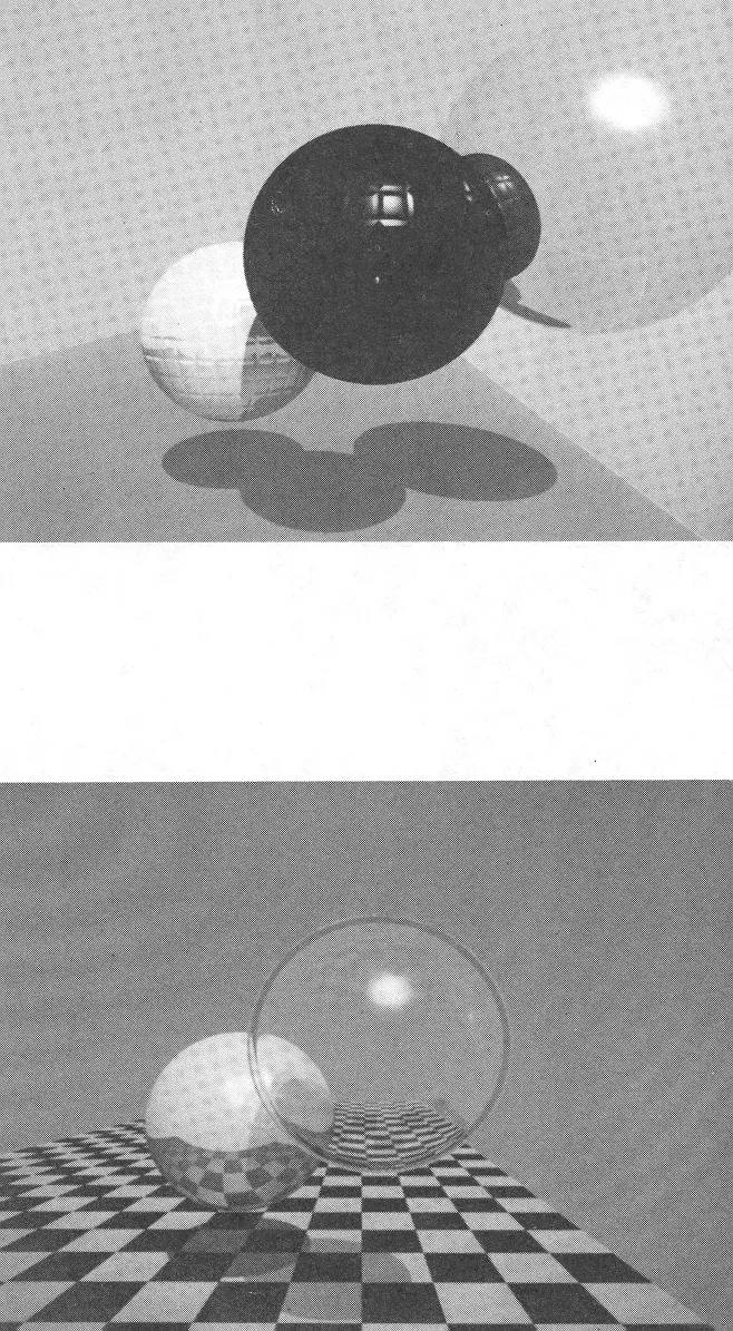
Turner Whitted: Reflection and Refraction, Original Paper, 1980.Turner Whitted / Communications of the ACM, 1980; Original illustrations, University of Utah Archives.View source ↗
Prompt
Transform this image into an early recursive ray tracing render, with clean geometric surfaces, mirror-polished highlights, glasslike refraction on suitable existing elements, and reflections nested within reflections. Use crisp cast shadows, precise perspective, smooth synthetic shading, and restrained environmental detail. Keep the original subject and composition.
[Rays2track visibility], [reflection, and refraction through the scene].
Example
Turner Whitted: early bullet test scene.
Try it out
Compare aglass ball against apatterned background.
Background
Whitted's An Improved Illumination Model for Shaded Display was introduced in 1979 and published in Communications of the ACM in 1980. The recursive tracking of reflection and refraction rays provided acrucial step towards consistent specular and transparent surfaces. Earlier ray-tracking techniques preceded this; therefore, the slide does not claim to have invented all ray tracking in 1980. Modern renderers combine these fundamentals with more comprehensive light transport models.
Distinction
Ray tracing is acomputational principle, not auniform look. Simple recursive ray tracing does not automatically calculate every form of indirect lighting.
Aftermath
Light behavior can be systematically simulated instead of being faked for each surface individually.
Further examples · 7 images
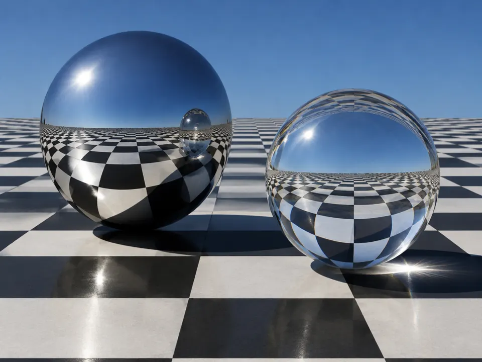
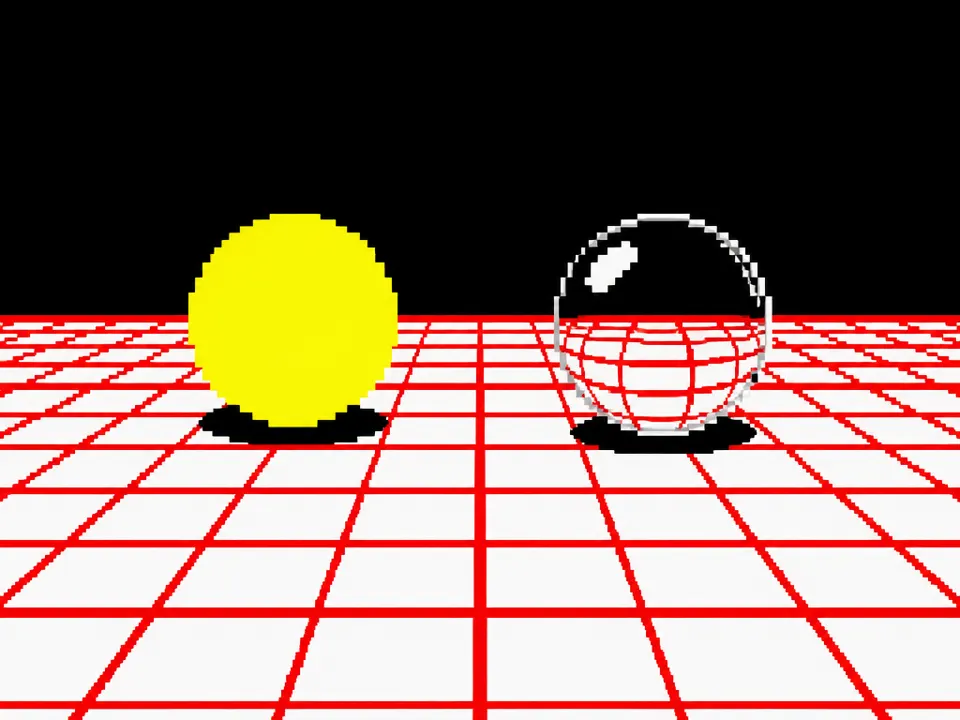
02Glasses 800 editVarious glass containers demonstrate multiple levels of refraction and reflection. The complex light paths through the liquids and glass represent modern applications of recursive ray tracing fundamentals.Gilles Tran · Public domain · Wikimedia Commons03Spheres and CheckerboardA glass sphere refracts the background while a reflective sphere mirrors it. This setup demonstrates Whitted's algorithm for tracking secondary rays to calculate precise transmission, reflection, and shadows on a floor plane.Phrood · CC BY-SA 3.0 · Wikimedia Commons04Wp mouse(dachris)A rendered scene containing a transparent sphere that exhibits both reflection and refraction. This demonstrates the recursive tracking of rays to produce consistent specular highlights and distorted background visibility through glass-like geometry.Dachris · CC BY-SA 3.0 · Wikimedia Commons05Rendering techniques example, ray tracing, low quality, POV-RayThree stylized cows rendered with different properties. The transparent cow on the right shows clear refraction and internal reflections, demonstrating how rays are tracked through geometry.KaiaVintr · CC BY-SA 4.0 · Wikimedia Commons06AI illustration: Reflective and refractive spheres sit on a checkerboard planeReflective and refractive spheres sit on a checkerboard plane. The image displays the distinct spatial logic of rays bouncing between objects and passing through glass.Illustration generated for the Atlas (AI)07AI illustration: A low-resolution render shows a solid sphere and a transparent sphere oveA low-resolution render shows a solid sphere and a transparent sphere over a grid. It replicates the specific 1980 Whitted test scene featuring refracted grid lines.Illustration generated for the Atlas (AI)
Question
Why is a shiny sphere in front of a pattern a useful test?
Show possible answer +Hide answer −
The pattern makes reflection, refraction, and geometric distortion immediately visible; errors are more easily noticed than against ablank surface.