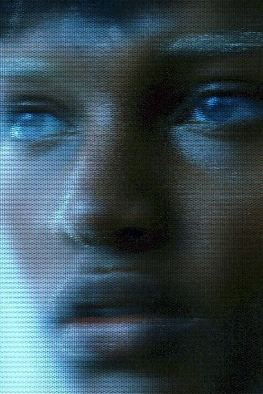
CRT scanlines. CRT everyday life of the 1980s; later retro vocabulary.
Typeface · Share Tech
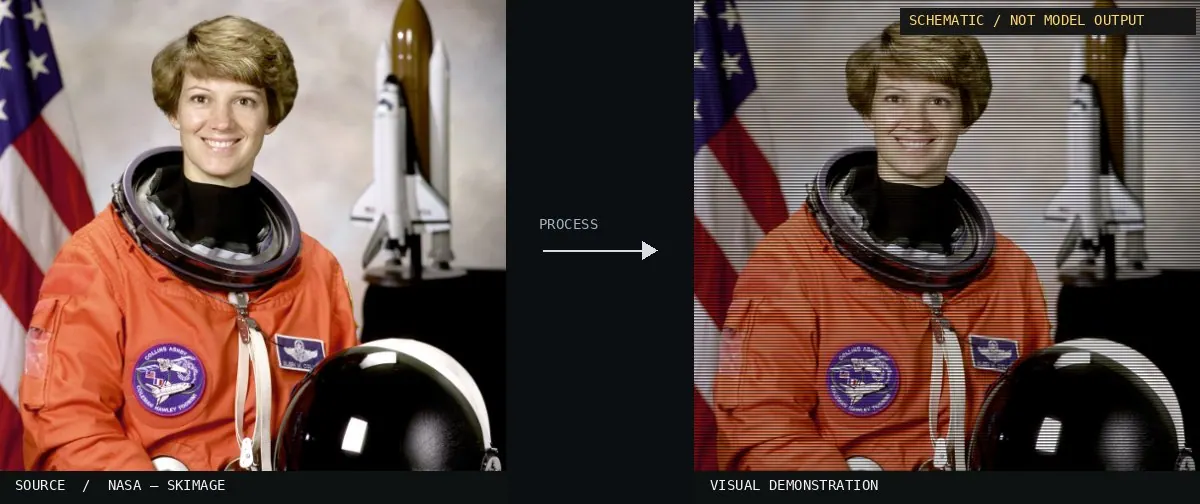
CRT/TV look: current digital effect demonstration.Digital effect demonstration; multiple CRT features combined.View source ↗
Prompt
Apply a CRT scanlines effect, covering the image with fine alternating bright and dark horizontal bands. Add subtle red-green-blue phosphor structure, gentle highlight bloom, slightly curved screen geometry, softened corner focus, and deep but luminous blacks without heavy tape tracking damage. Keep the original subject and composition.
Test the same look in small, large, and in motion.
Background
The line structure is part of the display on cathode ray tubes and is distinct from the content of the recorded video. The 1980s represent the everyday experience with television and computer monitors. Current tools elevate this to an aesthetic level. The digital process describes its TV effect as acombination of scanlines, pixel grid, color distortion, noise, and warping. For comparison, it is helpful to activate these components one after the other.
Distinction
The CRT look additionally includes luminance, phosphor structure, or curvature. Auniform striped overlay is merely asimplified imitation.
Aftermath
Display features become agraphic texture once the original device disappears.
Further examples · 12 images
02Poryzoid scan line effect exampleA dark green monochromatic graphic is overlaid with a dense pattern of horizontal black lines. It illustrates how scanlines create an artificial texture that defines the visual aesthetic of early digital displays.ritcharnd moskow from Toshi Station, USA · CC BY-SA 2.0 · Wikimedia Commons03televisore e lettore di videocassette CRT, a colori, 14 pollici, da tavolo, a transistor - BSR TVP-900.The rear view of a 14-inch transistor television shows a deep plastic housing required for cathode ray tube technology. This hardware is the physical source of the electron beams that produce horizontal scanline structures.BSR (costruttore) · CC BY-SA 4.0 · Wikimedia Commons04televisore CRT, a colori, 26 pollici, da tavolo, a transistor - Bang & Olufsen Beovision LX2800 Type: 3718. (1)A 26-inch color CRT television is shown from the front with a curved glass screen. This display surface is where fine horizontal bands of brightness would appear to form the televised image.Bang & Olufsen (costruttore), Lewis David (designer) · CC BY-SA 4.0 · Wikimedia Commons05televisore CRT, a colori, 26 pollici, da tavolo, a transistor - Bang & Olufsen Beovision LX2800 Type: 3718. (2)The back of a large color television exhibits the characteristic bulk and ventilation slots of 1980s hardware. It represents the everyday consumer electronics that delivered the scanline-based viewing experience to homes.Bang & Olufsen (costruttore), Lewis David (designer) · CC BY-SA 4.0 · Wikimedia Commons06Videosignal scanlineA single line of a video signal displayed on an oscilloscope. It shows the electronic basis of the scanline technique, where a beam travels horizontally to construct a portion of the visual image.Shaddack · CC BY-SA 4.0 · Wikimedia Commons07Mini Star 416 - cathode ray tube with deflection coils-2212A standalone cathode ray tube with visible deflection coils. This component is the direct source of the scanline effect, using electromagnetism to steer the electron beam across the screen.Raimond Spekking · CC BY-SA 4.0 · Wikimedia Commons08Cathode ray tube with deflection coilsThis image shows the internal hardware of a cathode ray tube. The deflection coils visible around the neck are responsible for steering the electron beam to create the scanline pattern on the phosphor screen.Peter Hebels · Public domain · Wikimedia Commons09CRT Scanlines — machine versionSchematic or classical approach — not a trained AI model output.Atlas of Visual Effects10Television Scan LineThe image displays a series of colorful rectangular blocks across a black background. Each block exhibits visible horizontal divisions that represent the physical scanline behavior of a television display.Tristantech · CC BY-SA 3.0 · Wikimedia Commons11Digital-Jackal glitch artA regular grid of fine horizontal dark lines covers the entire composition. These parallel lines simulate the characteristic row spacing of a cathode ray tube display, creating a mechanical texture over the digital illustration.Arielinson · CC BY-SA 4.0 · Wikimedia Commons12CRT Scanlines, applied to “Full-page portrait of Matthew in gold frame on purple background, with gold, gre”A framed portrait of Matthew appears behind a grid of thin black lines. The horizontal gaps between pixel rows simulate the electron beam pattern of a cathode-ray tube.Scan by NYPL (photo); processed for the Atlas · Public domain · Wikimedia Commons
Question
Which level does a scanline simulation primarily change: image content or representation?
Show possible answer +Hide answer −
It imitates the display of the image on araster display, regardless of which subject is shown.